1. Introduction
A technical photograph is any image that serves as an aide for describing a science, technology, engineering, or math – related apparatus or sample. Ideally, this kind of photography helps a viewer obtain an accurate understanding of the subject matter and the objects it interacts with in the surrounding environment. However, the intended message can easily be lost if the process of capturing the image is not thoughtfully planned.
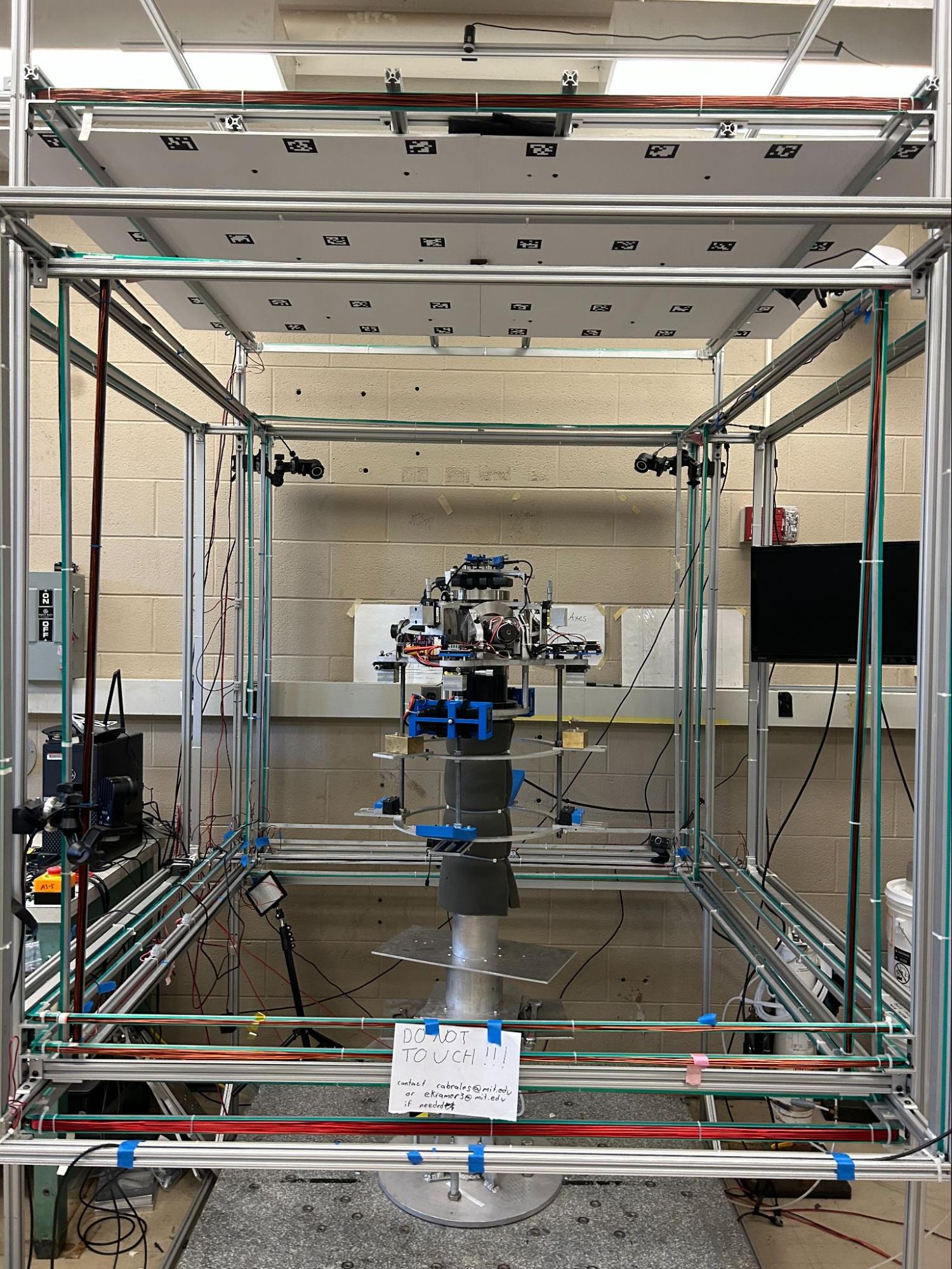
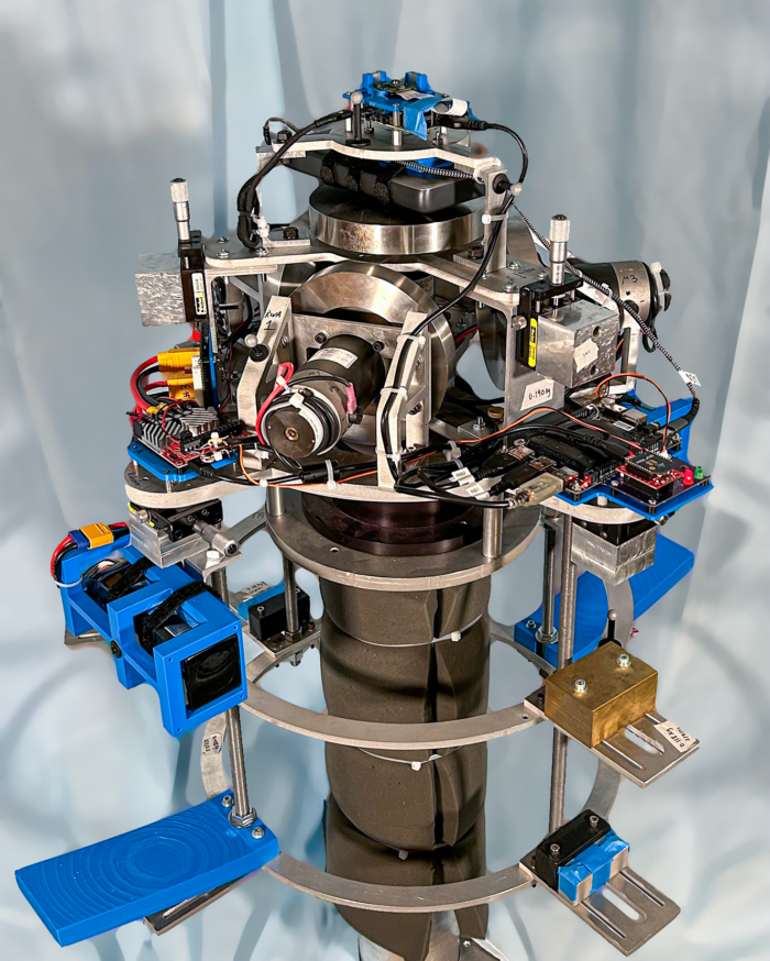
Figure 1. An unplanned (left) and planned (right) technical photograph of the Dynamics and Control Testbed (DCT) in the MIT Space Systems Laboratory (SSL).
2. Criteria for Success
- The technical photograph has a clear and easily extractable message.
- The subject of the technical photograph captures the attention of the viewer and portrays all essential components described in an accompanying caption or text.
- Features that provide necessary context for the primary subject, if any, are present and easily interpretable in the photograph.
- Features in the photographed scene that detract from the intended message have been removed as much as possible from the technical photograph.
3. Purpose
The purpose of this CommKit is to provide a stepwise approach to planning and executing a technical photograph. The stepwise approach involves consideration of three photographic dimensions – composition, lighting, and editing – that can maximize the success of technical photographs by making the photographer’s intended message clear and easily extractable. Common technical photography subjects include hardware testbeds and test samples.
4. Intended Audience and Context
Technical photography appears in a variety of mediums including academic journal articles, conference posters, and PowerPoint presentations. Typically, conference posters call for simple imagery whose intended messages can be extracted in the few moments a conference-goer scans through content whereas imagery in journal articles can be more detailed due to the expectation that it will be studied more thoroughly by the viewer. Additionally, while this CommKit is primarily intended to aid capture of photographs of static scenes, much of the discussion can apply to capturing dynamic scenes with video that can be especially useful in PowerPoint presentations. See links in the reference section for specific guidance on video.
As discussed in the technical photography blog post, it is important to acknowledge the following common limitations to capturing quality technical photographs:
- You may have limited accessibility to framing perspectives due to physical space constraints.
- You may not be able to control lighting conditions due to risks of negatively impacting the research project.
- There is variability in the capabilities of the cameras being used to take technical photographs.
These limitations may all be present to varying degrees or not present at all. The key takeaway is to consider which, if any, of these limiting factors are present in your scenario because this knowledge will constrain the possible approaches you can take to capturing your technical photograph.
5. Recommended Equipment
Control of camera settings including exposure time, aperture (f-stop), and ISO offer the most flexibility in capturing technical photographs. The exposure time refers to the amount of time the camera’s sensor is exposed to light from the scene and is usually controlled by a mechanical or electronic shutter, hence the term shutter speed, which is often used interchangeably. Aperture is the physical size of the hole through which light enters the camera lens. The ratio of the lens focal length to the aperture diameter is the f-stop. A large f-stop value refers to small aperture openings while a small f-stop value refers to large aperture openings. ISO is a measure of the sensor’s sensitivity to incoming light. A larger ISO value results in a higher sensor sensitivity. While cell phone cameras are continually offering more camera setting control to the user with each new model release, DSLR or mirrorless cameras still offer the most control in crafting the desired image. Nevertheless, the approach and examples described in this CommKit are written primarily with cell phone cameras in mind given the reality that DSLR or mirrorless cameras are less accessible.
With knowledge of scenario-specific constraints described in the intended audience and context section in mind, a useful toolkit for capturing a wide variety of technical photographs is as follows:
Required:
- Camera – smartphone or professional camera
- Stable camera stand – tripod, boxes, bench
- Controllable lighting – LED panels, spotlights, flashlights
- Phone capture:
- IOS:
- ProCam
- Yamera
- Manual Cam
- IOS:
-
- Android:
- Open Camera
- Camera FV-5
- Android:
- Photo editor:
- IOS:
- Adobe Photoshop Express (free)
- iPhone photos app editor (free)
- Adobe Lightroom (free)
- IOS:
-
- Android:
- Adobe Photoshop Express (free)
- Snapspeed (free)
- Adobe Lightroom (free)
- Android:
Recommended:
- Remote capture functionality – timer on smartphones or remote shutter release on professional cameras
- Single tone background – bed sheet, poster board, paper
6. Creating a technical photograph – the photographic dimensions
One way to summarize the criteria for success described in section 2, is to create imagery that maximizes the signal to noise of the photographer’s intended message. Composition, lighting, and editing are three photographic dimensions that can maximize the success of a technical photograph in achieving this overarching objective. Each of these dimensions is described below in reference to a photograph design space. Creating a photograph is similar to how an engineer performs a design space exploration for a new product. An engineer will attempt to narrow down the number of possible design solutions for their particular challenge to a smaller subset based on a list of desired parameters. The reduction in dimension of possible designs to a subset of preferred solutions is systematic in nature through some predefined process.
Planning technical photographs can be approached in a similar, systematic way in which photographic dimensions of composition, lighting, and editing are the parts of a photograph’s design space to be reduced. For example, in the planned technical photograph of the Dynamics and Control Testbed (DCT) in figure 1, several decisions were made in the planning phase that eventually produced the final image. Examples of these decisions include selection of a slightly downwards-looking angle with a uniform background for composition, a front-lit lighting setup that casts gentle shadows behind the primary subject, and exposure adjustments in photo editing software to equalize brightness across the testbed. It is worth noting that rarely will there be a single possible solution within the set of reduced designs. This is expected and where a photographer’s expertise and personal choice can select a unique final design. With the photographic design space put into context, let’s define each of the photographic dimensions.
6.1. Composition
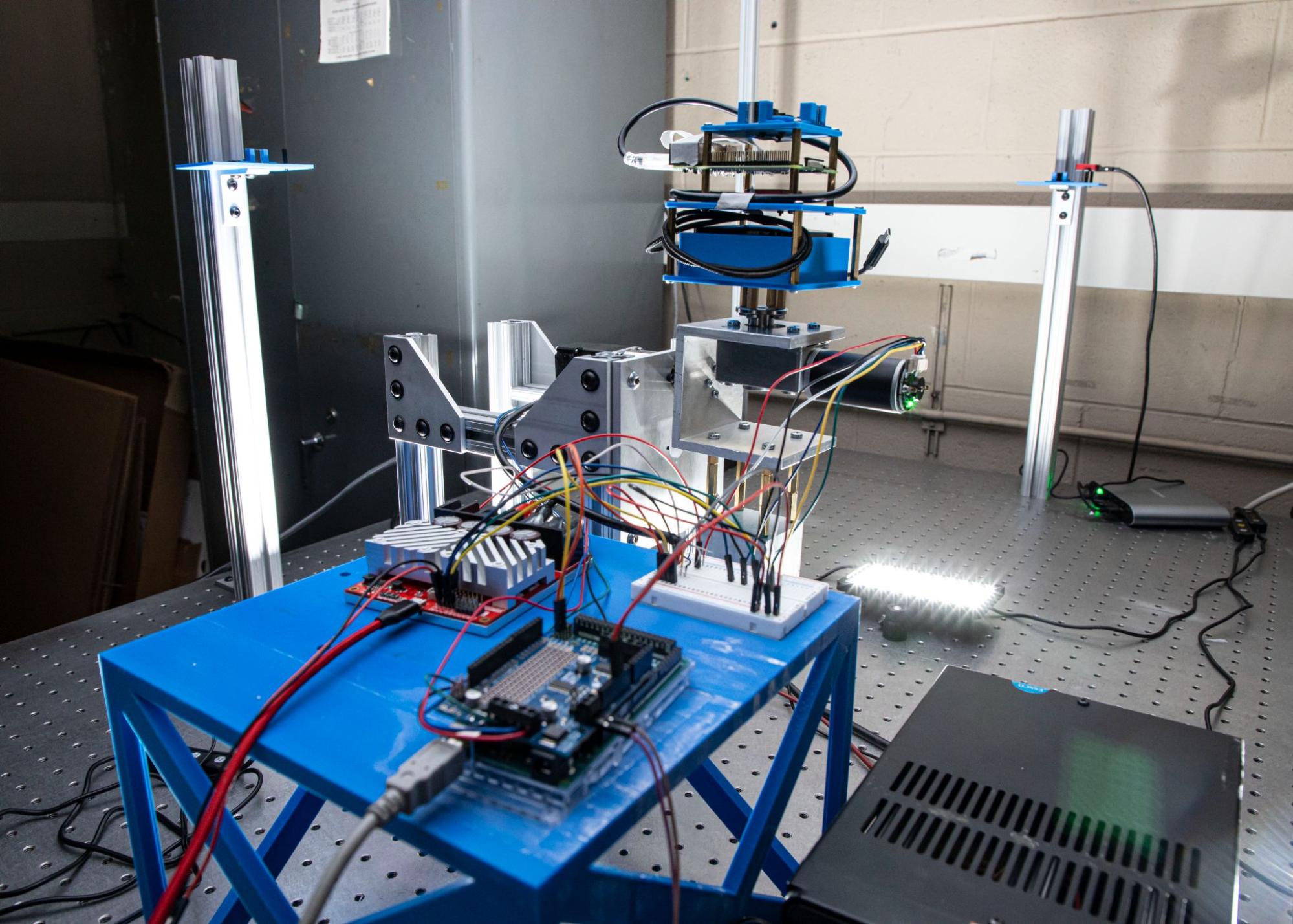
Figure 2. Although the attitude determination testbed (ADT) is shown in both of these images, a wide (left) and tight (right) perspective changes the composition of these technical photographs drastically. The wide perspective suggests that the motor controllers in the foreground are the primary subjects whereas the tight perspective suggests that the camera assembly is the focus.
Photographic composition involves the consideration of all elements present in a photo and their interactions. When I think of photographic composition, one word comes to mind: identification. Identification involves a process in which the photographer determines a technical photograph’s overarching intended message, its subject matter, and what the important features in the surrounding environment are. Note that the identification process occurs prior to capturing any photographs. Determining the photo’s overarching intended message is the first step of the process and is essential to creating an image with a clear and extractable message. The most common overarching intended message is is to effectively aide accompanying text-based or verbal descriptions of a physical object such that its function and interactions with other objects in the surrounding environment can be clearly understood. The second step of identification is to determine the subject matter, whether it’s a single physical object or a function of multiple objects working together in a system. The subject matter should be featured prominently because it is the focus of the photograph’s overarching intended message. The third and final identification step is to determine the important interfaces with secondary objects in the scene that enable the subject matter’s function. Note that only important interfaces should be considered, such as anything that is required to be present for the subject matter to function. In some instances, there may be no important interactions with other objects, while in others, several interactions may be occuring. Through the identification process, the photograph’s design space has significantly reduced in dimension and we are now prepared to achieve the criteria for success. Figure 2 shows examples of two different compositions of the same hardware testbed, the attitude determination testbed (ADT). While some of the same physical features are present, the different compositions convey different messages between the two images. For an image meant to showcase the testbed as a whole and to convey the interactions between the camera subsystem and the motor subsystem, the left image is better suited. On the other hand, for an image meant to showcase a more focused perspective of the camera subsystem and the presence of an optical metrology subsystem on the camera platform, the right image is better suited. Notice how changes in camera location and viewing geometry change the prominence of objects, and therefore what is perceived to be the primary subject of the image.
6.2. Lighting

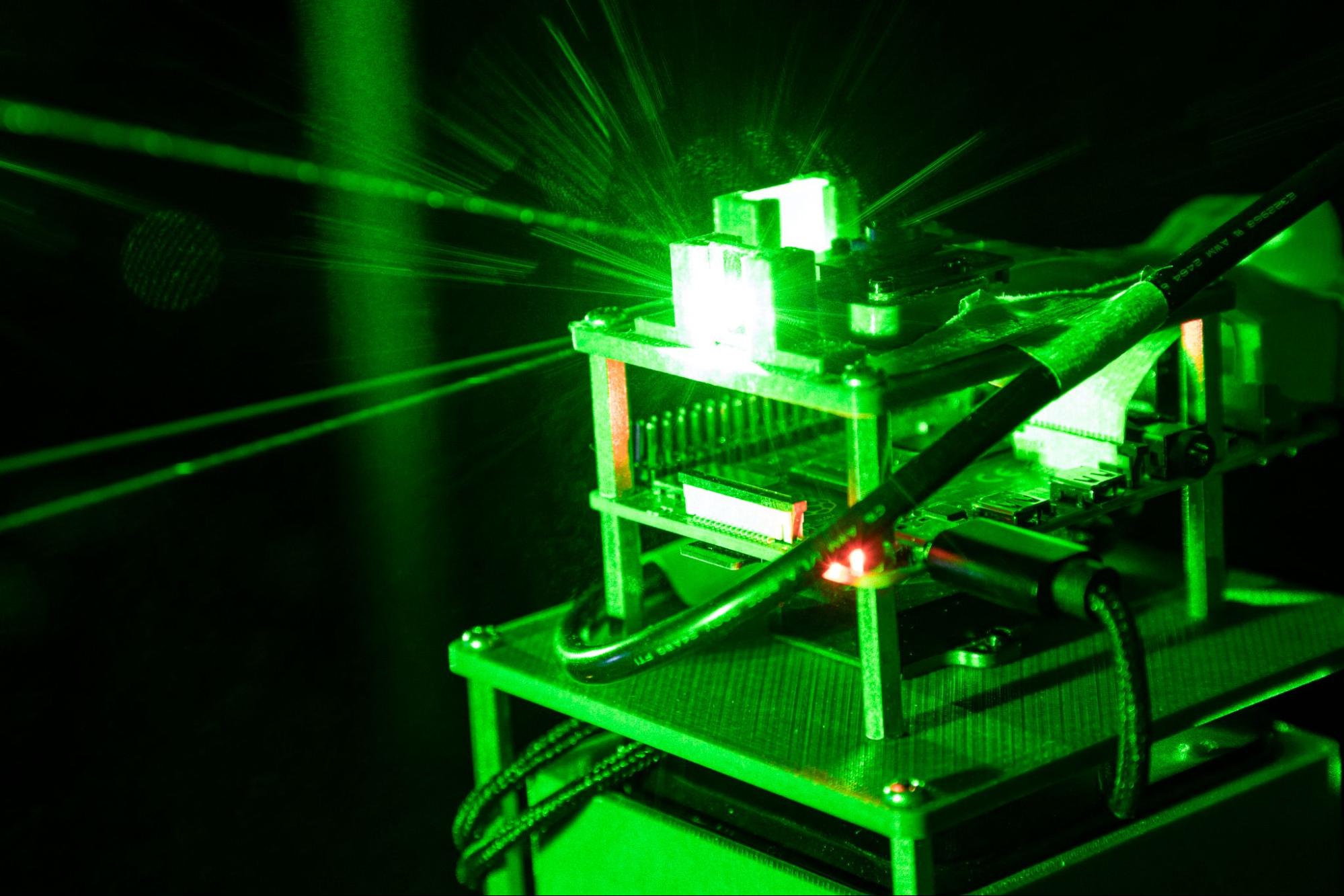
Figure 3. Different lighting setups can completely change the message of a technical photograph. Although the same hardware is present in both images, the green laser light in the right image makes the optical metrology feature of the camera assembly much more apparent to the viewer compared to the left image.
Often overlooked, lighting is an essential dimension that dictates how a viewer is guided throughout an image. Lighting has the power to draw attention to or away from objects in the scene as well as create connections between interacting features. Generally, many technical photographs can be improved by simply adding to the amount of lighting present in the scene. Common facets of lighting include intensity, directionality, shape, and color. Oftentimes, the primary subject of an image will be illuminated with high intensity light to highlight its presence in the scene. Adding a form of diffuser, such as a semi-transparent sheet that is placed in front of the light source, can create a more homogeneous lighting profile for the primary subject when shadows and glare are a concern. The directionality of primary subject lighting can be selected based on whether the photographer wishes to draw attention to certain features of the primary subject while masking others in shadow, or whether a uniform lighting profile from all directions is desired instead. In settings where the photographer has full control of ambient lighting conditions, the shape may be controlled to convey interactions between multiple features in the scene through the use of a spotlight with circular or custom shape footprint. Differentiating between several illuminated regions of a scene can be accomplished using different color profiles.
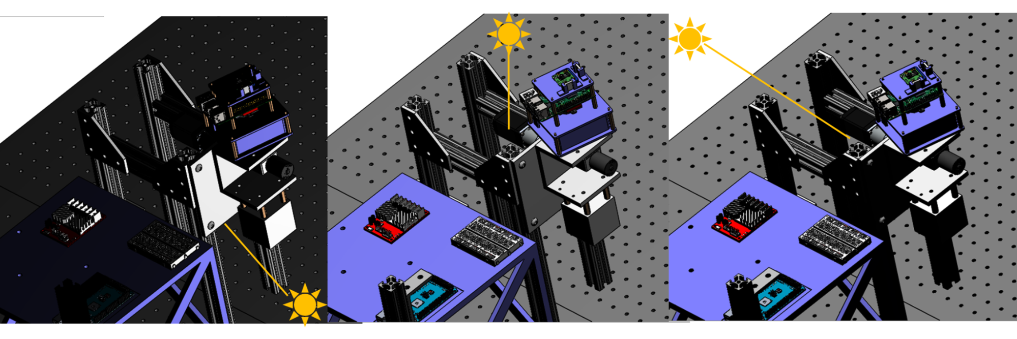
Figure 4. Directionality of light can be used to draw a viewer’s attention to certain objects in the scene while masking others. In the CAD assembly of the ADT shown above, the lighting direction is varied to demonstrate how the photographer has control over where shadows are cast and highlights are placed in the scene.
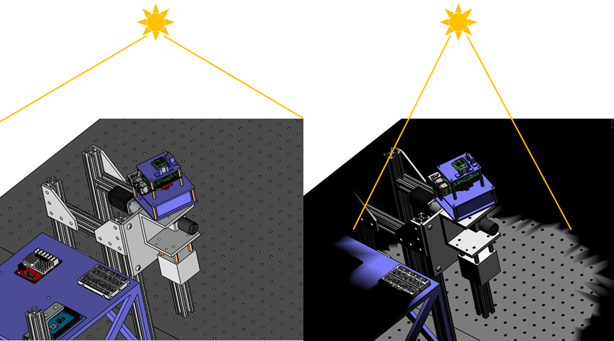
Figure 5. The shape of light can also be used to draw attention to particular objects in the scene, especially when dramatic contrasts between the subject and surrounding objects is desired. A light with no strong shape characteristics is shown to illuminate the scene equally in the left image whereas a more focused perspective is achieved in the right image where a circularly-shaped light is trained on the camera assembly of the testbed.
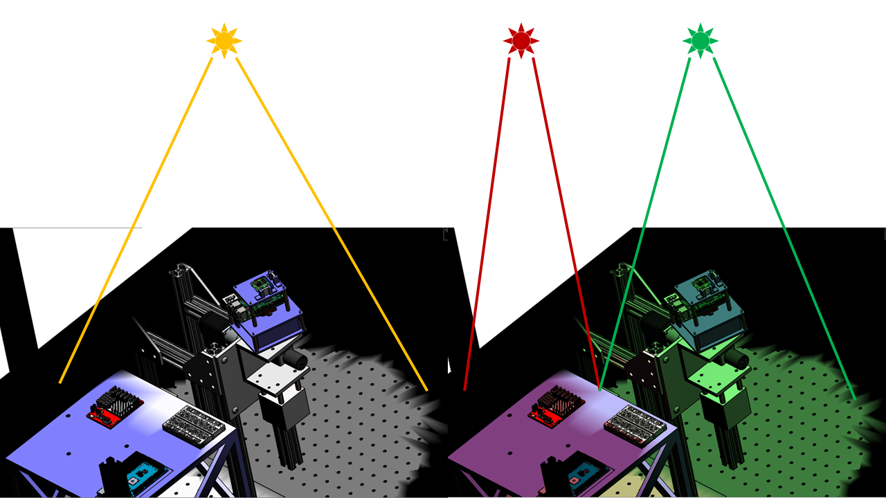
Figure 6. Control of light color is an effective way to differentiate features in a scene. While a single, white light source was used to illuminate the scene on the left, a red and green light source were used to differentiate the platform supporting motor controller electronics and the mounting fixture of the camera assembly.
In technical photography situations, simpler is often better when it comes to lighting when the goal is to clearly convey an intended message. However, knowledge of all dimensions available within the lighting parameter space can enable maximal success. The left image in figure 3 shows an example of the ADT camera subsystem as before. The lighting is uniform since an LED light panel is used to reflect light off a white poster board above the camera subsystem that scatters light equally in all directions. While the uniform lighting portrays the entire camera subsystem clearly in the left image, the right image of figure 3 uses different lighting approaches to draw attention to the planar mirrors mounted to the camera platform. The ability to control the lighting conditions in this scenario enable the use of lasers to both reveal the function of the planar mirrors, but to also visually highlight measurements of the deviation in angle between incidence and reflected rays.
6.3. Editing
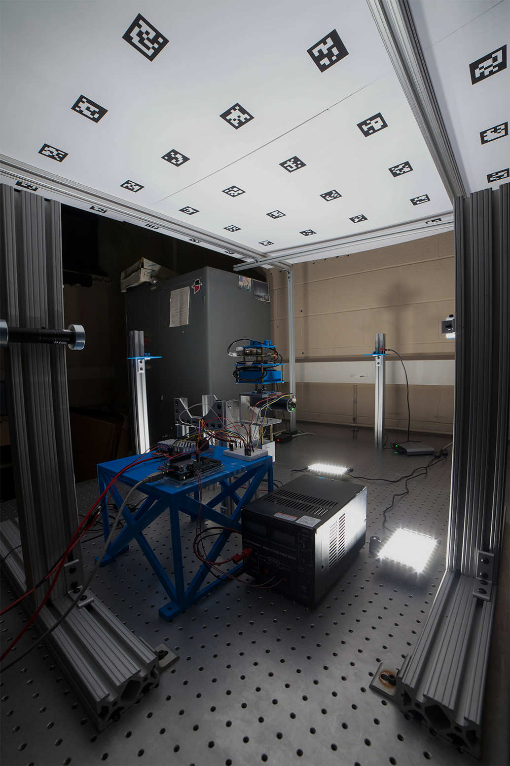
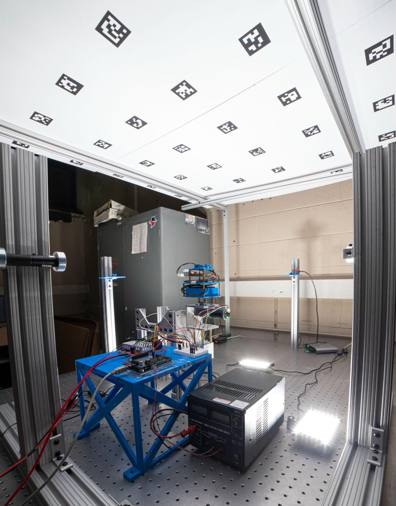
Figure 7. The image on the left is straight from the camera, unedited. The image on the right is edited. Empty space at the bottom and top of the photograph was cropped without losing any data that contributed to the overall message of the photograph. Exposure adjustments were made to make shadowed regions more visible to the viewer.
While lighting is often overlooked, editing is often relied upon too heavily. It is true that photographs can be altered without limit with today’s editing tools, especially with the advent of generative AI in Adobe Photoshop and other editors. However, rarely does the amount of editing have a direct relation to the success of an image in conveying an intended message. Through responsible use of editing tools, a photographer can maximize the signal to noise ratio of an image without misleading the viewer. Within the context of this CommKit, maximizing a photograph’s signal to noise ratio refers to any action that helps accomplish the original objective of the photograph and removes unneeded information. Responsible use of editing tools entails actions that do not alter the message of an image itself. For example, cropping features out of an image that have no bearing on the intended message, increasing or reducing contrast so that subjects are highlighted or masked, and adjusting the presence of texture using smoothing filters are three common editing tools that can help accomplish a photograph’s objective when used responsibly. The left image in figure 7 is an unedited image whereas the right image is edited. The most noticeable difference is the crop between the two images. Notice how very little, if any, pertinent information for understanding the subject – the attitude determination testbed – and interactions – power, lighting, and optical fiducial markers – in the image was lost due to the crop. Lighting and texture adjustments are also apparent between the two images. The edited image on the right shows more detail in the foreground where the platform supporting motor controllers is present, which is relevant to understanding the interfaces at play in the scene.
The following section offers a real example of creating a technical photograph. The approach described can serve as a template for a photograph design space reduction.
7. Guided Example
With an understanding of how composition, lighting, and editing can maximize the success of a technical photograph. Let’s consider how we can apply these dimensions to the following objective: Photograph the Xbee wifi communications device on the Dynamics and control testbed (DCT) in the MIT Space Systems Laboratory (SSL) whose purpose is to receive a remotely transmitted stop command in emergency situations. The Xbee device location is annotated on the left in figure 9. The right of figure 9 shows an image of the Xbee device captured with an iPhone 14 without any prior planning.
Figure 8 below shows a behind-the-scenes view of the equipment setup used to capture the photograph on the right of figure 1 at the beginning of this CommKit. It involves most of the items in the technical photography toolkit identified in the list above. A light blue sheet is used to eliminate the presence of distracting, unimportant features in the scene by offering a relatively featureless backdrop. Two LED light panels are used to light the testbed such that the perspective from which it is photographed is uniformly illuminated. The presence of shadows is apparent due to the usage of fairly directional lighting. However, this was considered to be an acceptable tradeoff between providing uniform lighting to the subject and eliminating the presence of distracting background features. Note the placement of LED panel tripods on lab chairs for creating undistorted, eye-level shadows as opposed to long, distorted shadows. It is encouraged and commonplace to use any and all resources available to construct your desired photography conditions.
Although it is not visible in figure 8, an iPhone 11 was used to capture the planned technical photograph in figure 1. The photograph was captured with the iPhone hand held because the illumination was strong enough to not require a long exposure time (exp time < 1/60 s) rendering the use of a stable camera stand unnecessary in this scenario. Another tool from the photography equipment list not pictured in figure 8 is a photo editor. The camera raw filter in Adobe Bridge was used to crop the image and lighting and texture adjustments were applied to the planned technical photograph in figure 1. In the majority of photo editing cases, the Adobe camera raw filter will offer all the functionality needed to put the finishing touches on your technical photograph. The Adobe camera raw filter can be accessed from within Adobe Photoshop or within Adobe Bridge. Adobe Lightroom also offers editing functionality that aligns very closely with the camera raw filter. All of the Adobe photo editing products mentioned are available through a free MIT student account as part of Adobe Creative Cloud. The iPhone photos app editor offers similar functionality to the Adobe camera raw filter as well.
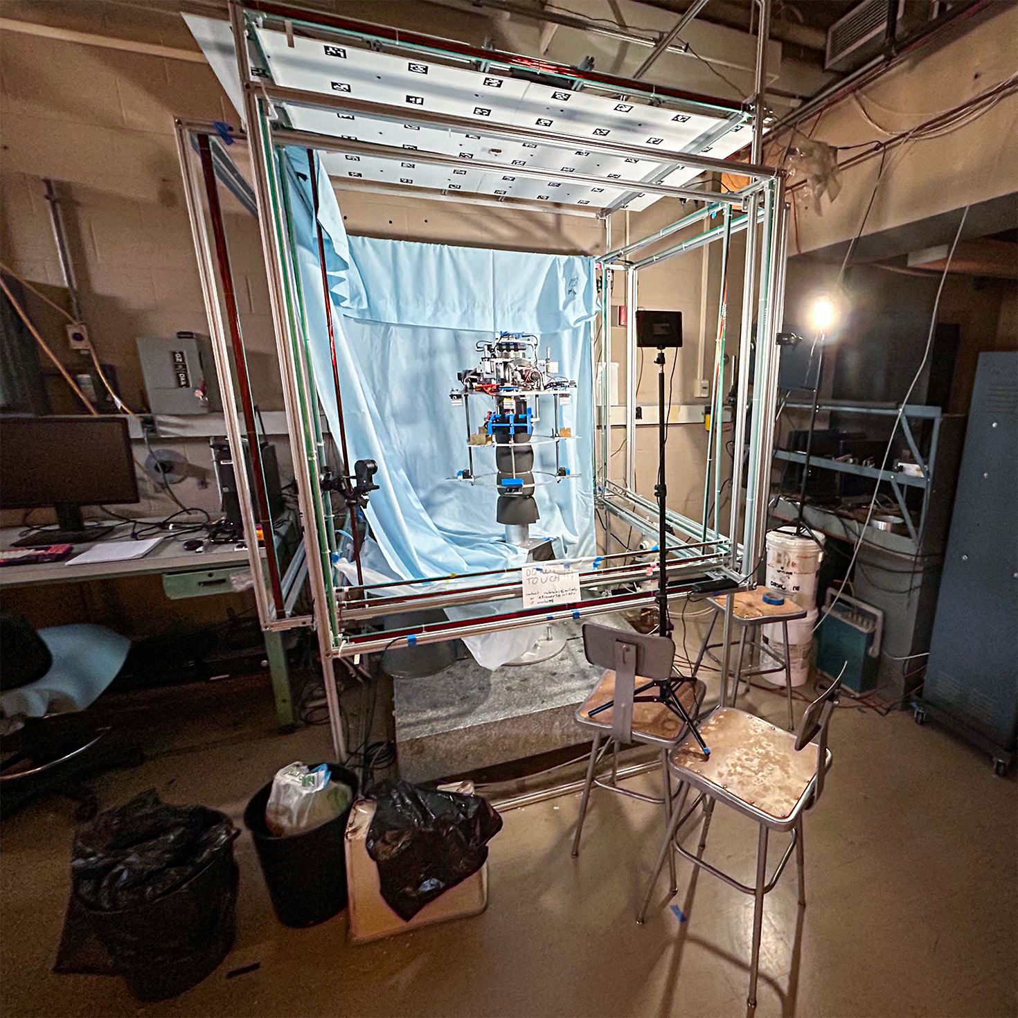
Figure 8. Photography equipment setup for capturing the planned technical photograph in figure 1 shown at the beginning of this CommKit. A blue sheet was draped over the testbed’s Helmholtz Cage to create a uniform background while two LED panel lights were used to provide diffuse, homogeneous lighting of the testbed.
At first glance, the unplanned photograph seems to accomplish the stated objective, and for some use cases including an informal photo shared with a colleague, no further photographic iteration would be necessary. However, intentional application of the photographic dimensions discussed in the previous section can transform this unplanned image into one suitable for formal sharing applications including a journal article or conference presentation.
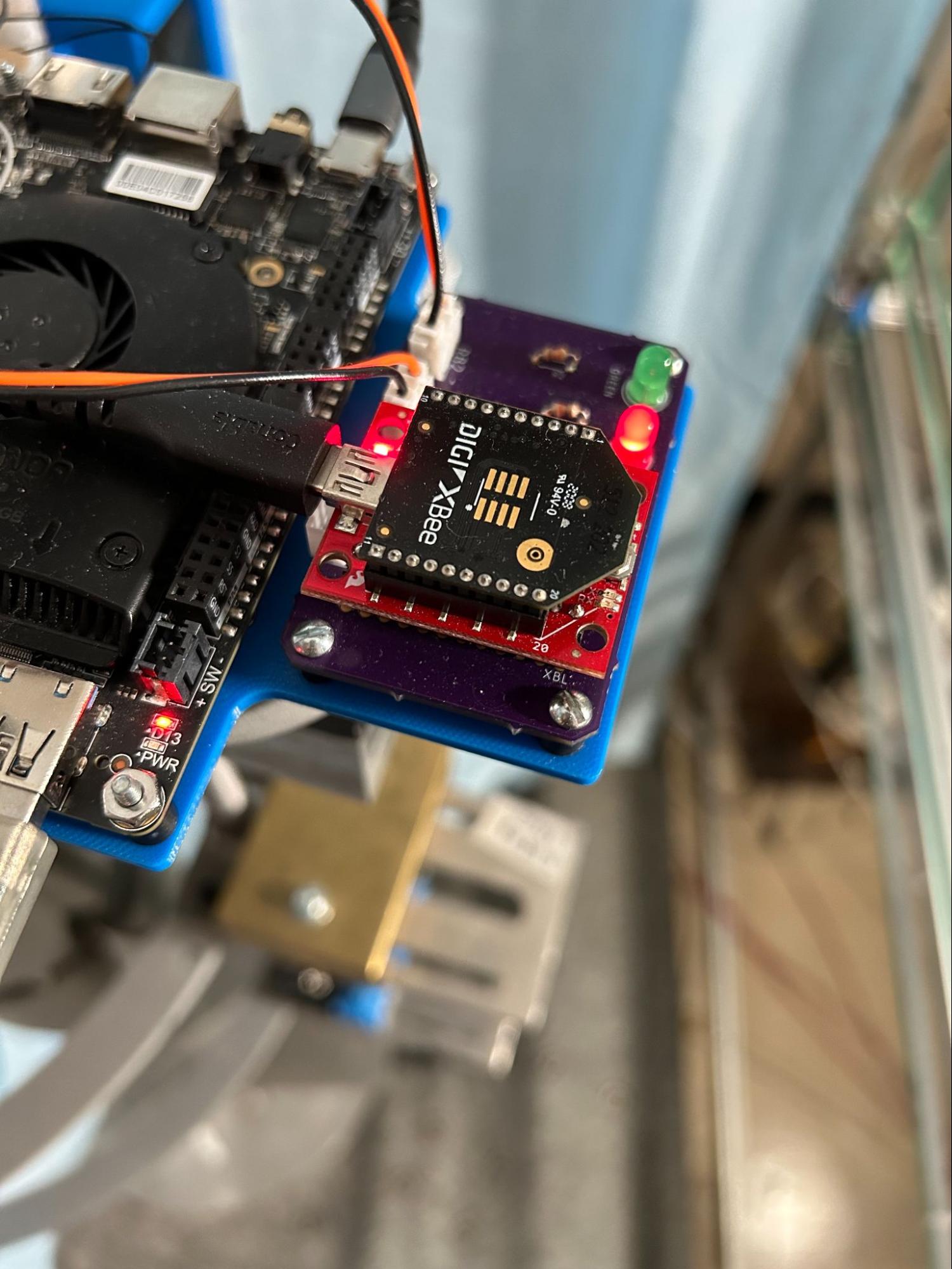
Figure 9. Location of the XBee device on the DCT annotated by a red box in the left image and an unplanned image of the XBee device in the right image.
With the objective at hand, the question that comes to my mind is, “what is the star and what is the supporting cast?” Unsurprisingly, the Xbee device is the primary subject and should therefore be featured prominently in the foreground scene. To identify the supporting cast, I asked myself, “what enables the Xbee to perform its primary functions?” The LattePanda single board computer that communicates the emergency stop command to the rest of the testbed and the custom-made purple printed circuit board (PCB) with two LED lights that provides power and identifies the state of the Xbee device came to mind and should therefore be featured in the background. The Xbee is featured prominently in the unplanned photograph and parts of the background subjects are visible. However, to more effectively convey how the Xbee performs its primary function of enacting an emergency stop on the testbed, a change in composition according to the identified primary and secondary subjects is necessary. Figure 10 shows an adjusted composition that more clearly showcases the interfaces between the Xbee and supporting features captured in the iPhone 14’s portrait mode. Portrait mode enables control of the size of the camera lens aperture. Adjustment of the aperture size has multiple effects, namely blurring portions of the image, and is discussed in the following paragraphs. The Xbee and supporting devices are visible in figure 10 with the interfaces between them, for example the USB cable connecting the Xbee device to the LattePanda, easily distinguishable.
A follow-on question that comes to my mind is “are all useful descriptive features of the scene visible and clear in the image?” Isn’t it frustrating when a reference is made to something that is not easily distinguishable in any form of technical media? A slight adjustment to the composition shown in figure 10 can improve the chances of the viewer fully grasping the purpose of each of the components contributing to the critical function of the Xbee emergency stop system. Notice in the right image of figure 10, which is an enlargement of the Xbee and PCB in the left image of figure 10, the annotations on the PCB board for the two LED indicator lights are not legible due to blur. Describing the function of the emergency stop system would be more successful if both a color and annotation reference could be made to indicate the state of the Xbee device.
Adjusting the f-stop in your camera settings changes the depth of focus, or amount of the image that is in focus. The f-stop is the ratio of the camera lens focal length to the lens aperture diameter. The f icon in the top right corner of the iPhone camera app enables adjustment of the f-stop in portrait mode. In this case, we would like to increase the depth of focus to improve the legibility of the LED light annotations. Larger f-stop numbers increase the depth of focus in the image while smaller f-stop numbers produce the opposite effect. The left of figure 11 shows the focus adjusted composition and the right of figure 11 shows an enlargement of the Xbee device. While the full-frame focus adjusted composition in figure 11 doesn’t appear significantly different than the full frame composition in figure 10, the LED light annotations are now legible in the focus adjusted case when comparing figures 11 and 10. Attention to small details such as the legibility of hardware annotations can maximize the probability that viewers fully grasp the intended messages behind your technical photographs.
My mind then turns its attention to lighting. In the case of photographing the Xbee, the lighting requirements are fairly straightforward and are mostly accomplished by the LED panel lighting setup described in the equipment section of this CommKit when capturing the image of the entire DCT. Ensuring that the lighting choices highlight the primary subject and supporting features of the image is satisfactory. I notice that the LattePanda is somewhat dark compared to the rest of the scene and there is a small loss of detail in its features. Given that this is not a significant lighting challenge, adjustment of shadow and black levels in a photo editor can remedy this.
The photograph in figure 11 is close to the final product, but not quite in my eyes. The final step of editing can put the finishing touches on this image. I open the image with the camera raw filter in Adobe Bridge and perform some adjustments as shown in the screenshot on the right in figure 12. As mentioned in the previous paragraph, the LattePanda appears dark with a small loss of detail in its features. To recover some of the information in the dark regions, I bump the “shadows,” “blacks,” and “exposure” slide bars to the right and the “contrast” slide bar to the left while keeping an eye on the image intensity histogram at the top. My goal is to nudge the data distribution in the intensity histogram to the right enough to reduce the amount of data registering pixel intensities near zero without clipping my highlights, or pushing the data with pixel intensities near the maximum value to the maximum. In a way, this adjustment has the effect of reducing the contrast of the image. In order to recover some of the contrast that’s been lost and maintain a sense of sharp texture, I bump the texture and clarity slider bars to the right. While the texture and clarity sliders primarily affect small and medium scale features in the image, they both generally increase the contrast of edges at their respective scales. At the levels shown in figure 12, I felt the lighting and texture adjustments served to effectively highlight features of the subject and supporting cast without adding any noise. As a last step, I cropped the image to remove the dark tones in the bottom right corner while ensuring all interfaces between the XBee and other components remained visible. At this point, the image is complete. It conveys the intended message of the emergency stop system effectively, ensures all important interfaces are distinguishable, and reduces the presence of unwanted distractions. You are now ready to apply a similar systematic approach to capturing your own technical photography!
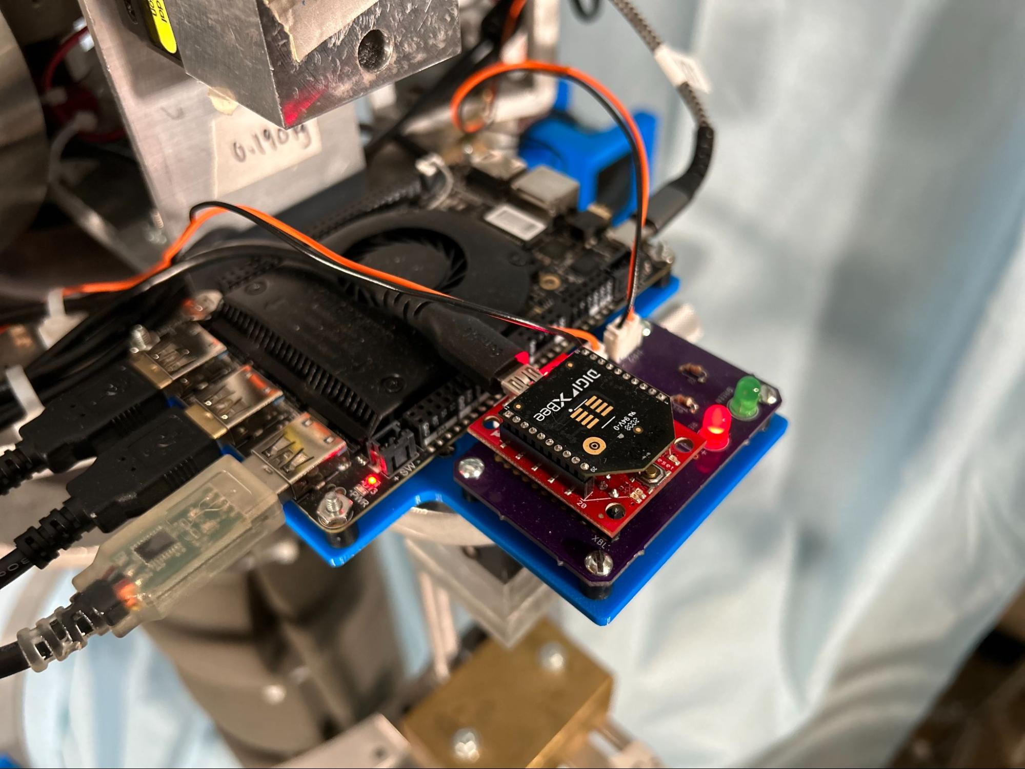
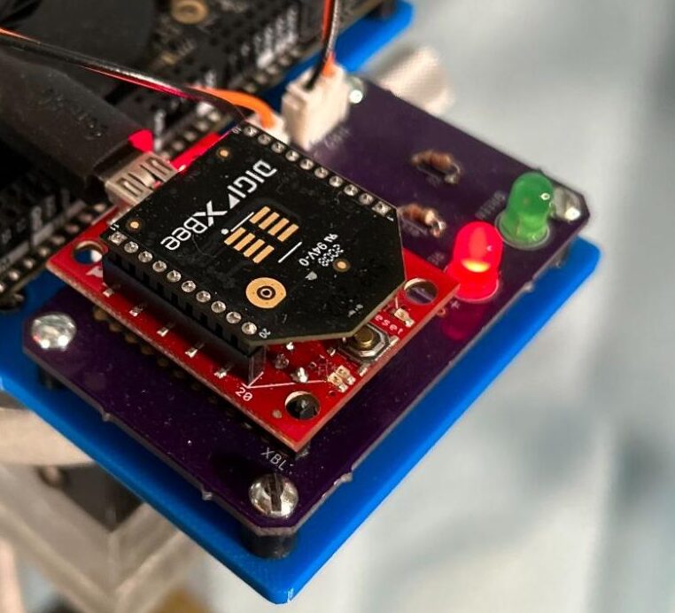
Figure 10. Adjusted composition where the primary subject, the XBee radio, is featured prominently and its interfaces, such as connections to the LattePanda, are visible. The image on the right is an enlargement of the XBee radio in the left image.
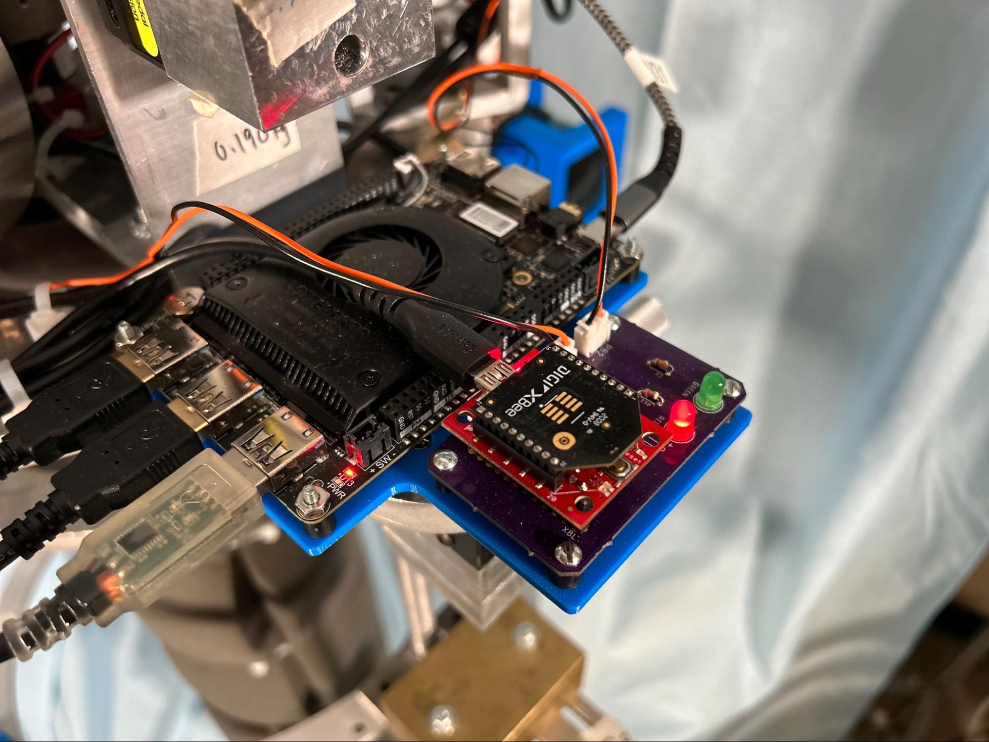
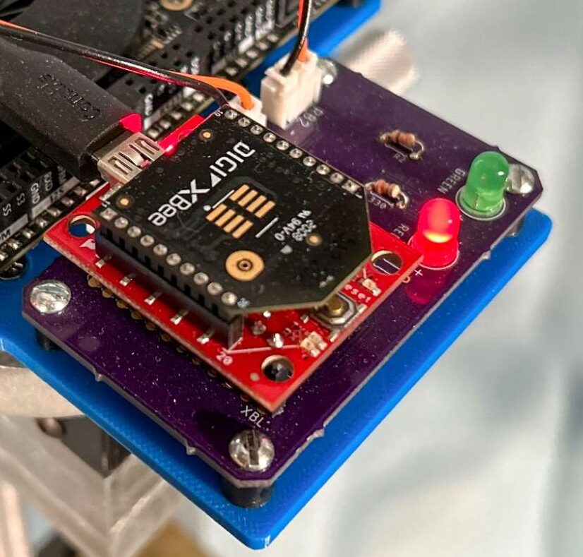
Figure 11. Focus-adjusted image of the XBee device. While the image on the left does not appear significantly different from the left image in figure 10, emergency stop LED labels are more legible in the enlarged image of the XBee device on the right compared to the enlargement in figure 10.
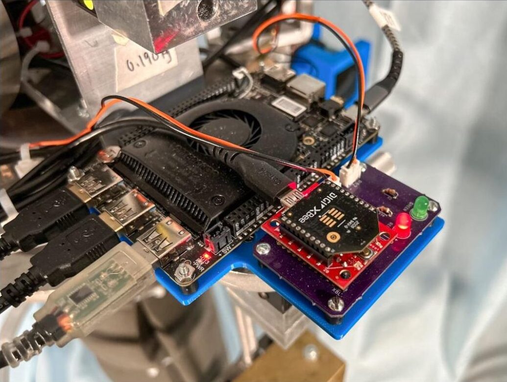
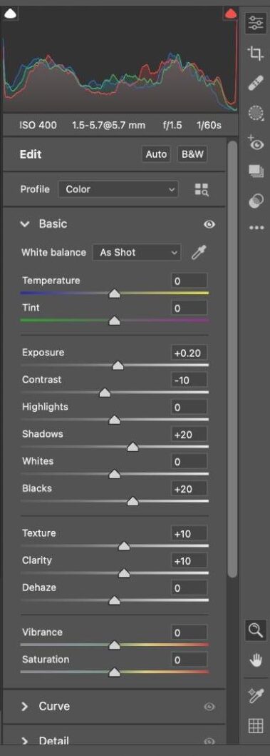
Figure 12. Edits to the image shown in figure 11 were performed to retrieve loss of detail in darker regions. Adjustments to the exposure, contrast, shadows, and black level sliders are shown in the screenshot of the Adobe Bridge camera raw filter on the right. Slight adjustments to the texture and clarity sliders were also added.
8. Additional Resources
- Adobe Creative Cloud for MIT affiliates (includes Photoshop, Bridge, and other Adobe products)
- Phone photo capture apps:
- iOS: ProCam, Yamera, Manual Cam
- Android: Open Camera, Camera FV-5
- Phone photo editing apps:
- IOS: iPhone photos app, Adobe Lightroom, Adobe Photoshop Express
- Android: Adobe Lightroom, Adobe Photoshop Express, Snapspeed
- Felice Frankel – Science photographer with several published how-to books and research scientist at MIT
- Figure Design CommKit
- Youtuber Jared Polin videos on a myriad of photography and video topics